Call Us 281-940-KELM

Piping Vibration
Kelm Engineering
Piping vibration is a common problem in processing plants due to dynamic loading normally from connected equipment. Measuring and evaluating piping vibration can be challenging because there are no clear standards for vibration limits and once vibration is documented it is difficult to evaluate to determine if the line is at risk. A summary of common methods to document and evaluate piping vibration are provided here and the full paper will be presented at the Vibration Institute Triplex Chapter's Annual Seminar on Tuesday, April 9th 2019.
Author
Ray Kelm is a Sr. Consultant for Kelm Engineering, LLC located in Houston. He has a BSME degree from Texas A&M and a MSME degree from University of Virginia. Ray has spent the last 35+ years working with machinery dynamics and vibration analysis primarily in the petrochemical, power, and refining industries. He has investigated numerous cases where severe piping vibration has existed including a variety of situations where pipes fatigued and resulted in loss of containment.
Vibration Institute Triplex Chapter Annual Seminar
This paper will be presented in full at the Vibration Institute Triplex Chapter's 30th Annual Rotating Equipment, Reliability, and Vibration Analysis Seminar will take place Tuesday, April 9th. The seminar will be held at the MCM Elegante Hotel in Beaumont, Texas. Please visit the Triplex Chapter’s website to register and get more information.
How to Measure and Evaluate Piping Vibration
Piping vibration is a challenging problem to evaluate and can result in pipe fatigue failures when excessive. The biggest problem for the vibration analyst is trying to decide if the vibration amplitudes are acceptable or not!!! There are numerous references and standards that define acceptable vibration limits for rotating or reciprocating machinery, but on limited resources to help the vibration analyst evaluate measured piping vibration.
This paper attempts to describe some basic methods for measuring and evaluating vibration to determine if the amplitudes are acceptable. Analysis methods are also provided for a more detailed analysis when required.
How Much is Too Much?
This is the question that is at the heart of every case where piping vibration is measured. Normally, pipe that is vibrating excessively is connected to either rotating or reciprocating machinery so that the vibration is transmitted from the associated equipment. In some cases, the vibration is more of a forced response due to pressure pulsations in the process fluid. For either case, the vibration response is frequently amplified due to the dynamics of the piping system that is connected to the equipment.
The main challenge with deciding on what the practical limits are for piping vibration is that the limit is actually a stress limit on the pipe wall and not directly a vibration limit. So the challenge becomes finding a way to relate vibration to stress limits for a specific piping system layout.
For example, a system with a very flexible pipe would have very high allowable vibration because the flexibility of the pipe will allow large motion without producing a lot of pipe stress. Alternatively, lower piping vibration for more rigid piping systems can produce higher stresses and result in failure at lower vibration amplitudes.
The most general relationship between piping vibration velocity and stress can be found in ASME OM3 that was originally developed for the nuclear power industry. ASME OM3 describes how to relate piping vibration velocity to allowable stress, or more specifically what the maximum vibration velocity is on a section of pipe to comply with ASME piping code. ASME OM part 3 defines a pipe vibration screening methodology that can be used to assess severity by estimating pipe stress for a given vibration level. ASME OM3 defines a first screening level of 0.5 in/s peak and an allowable vibration equation that incorporates a given pipe layout and construction details.
How to Measure Piping Vibration
The easiest way to screen piping for acceptable vibration is to start at one end of a “run” and document the overall vibration velocity about every foot or so. The purpose of this screen is to identify the maximum vibration velocity on a specific run or section of pipe. Generally, this can be done by using a pipe route on a data collector, where you measure the vibration in two directions perpendicular to the pipe direction along the pipe to identify the maximum in any direction.
Once the maximum vibration and frequency have been identified, it can be compared to screening criteria to assess severity. ASME OM part 3 defines a common first screening criterion as 0.5 in/s peak. If the vibration exceeds this criteria, then a more detailed assessment is required to determine the actual vibration velocity limit.
Pipe Vibration Example
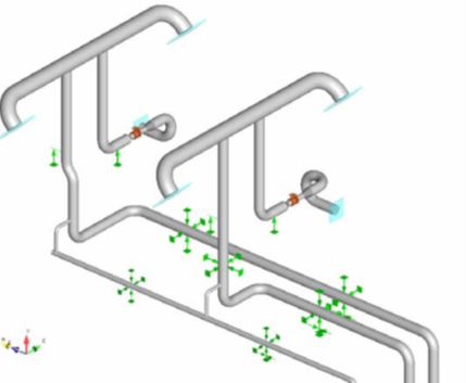 The vibration of this pipe system was documented every 3-5 feet to identify the maximum vibration and frequencies. The maximum vibration was evaluated to identify the locations of high relative movement. The small pipes interconnecting the larger ones are the at-risk lines due to these being where the highest stresses will be located.
Vibration that is steady and periodic is relatively easy to document, since any measurement will have often one or two peaks in FFT’s with obvious cause. Most common causes will be transferred vibration from connected equipment (pumps/compressors/etc.).
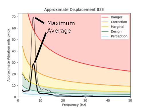
In some cases, the vibration is related to flow. When that occurs, it is often necessary to record the data an identify the “maximum” peak vibration over some period of time. An example of this is shown in here which resulted from two phase flow in a line downstream of a control valve.